


Correct D type rubber fender installation matches your contact line, substrate, and fixing method. Poor alignment or weak sealing causes loose hardware, leaks, or early tearing. At Zhonghaihang Shipping Supply, we supply rubber fenders for boats. We view installation from a field perspective, not just a drawing. This guide covers practical steps you can check on-site.
Basics: D Type Rubber Fenders and Typical Contact Zones
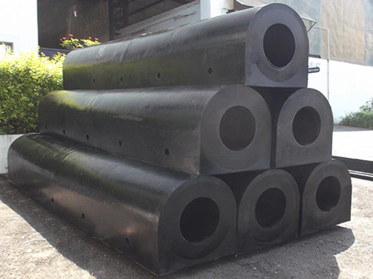
D type fenders work best when the flat back sits flush against the mounting face. The curved face must meet the vessel along the contact line. This “D” profile offers compact geometry and stable mounting. It is common on quay walls, piles, and workboats. However, performance fails if hull contact shifts too high or low. First, define where contact actually happens.
D Profile Basics
The flat back must sit flush against a wall or hull. This transfers load through the full footprint. The curved face compresses under impact. It spreads contact over a usable area. High spots or gaps cause uneven stress on hardware. A “flush fit” matters as much as fender size.
Typical Mounting Faces
Concrete quay walls often need anchors or embedded plates. Steel structures may allow through-bolting or welded brackets. Corrosion control is a priority here. Hull mounting requires careful hole control and sealing. This protects coatings and prevents leaks. Always plan for access. You need space for drilling, tightening, and inspection.
Learn More: What Are Rubber D Fenders Used For?
Planning: Site Conditions, Layout, and Fit Checks
Reliable layouts depend on real contact height, substrate condition, and access. Start with the operating envelope. Consider vessel types, approach angles, and water levels. Translate this into a marked berthing line. Confirm the mounting face handles, drilling and sealing.
Contact Height and “Berthing Line”
Base your markings on the vessel’s contact band, not aesthetics. Use a level or laser line for a consistent reference. If you serve multiple vessel sizes, define the highest and lowest contact points. Ensure your layout covers this range. If unsure, treat this as a verification task. Check with operations or look for prior rub marks.
Substrate Readiness
The mounting face must be flat. The fender must seat without rocking. Remove loose paint, marine growth, or dirt. This compromises sealing. Identify rebar zones or embedded plates before drilling concrete. Confirm rear access for through-bolts. If unavailable, use anchors or brackets.
Spacing and Coverage
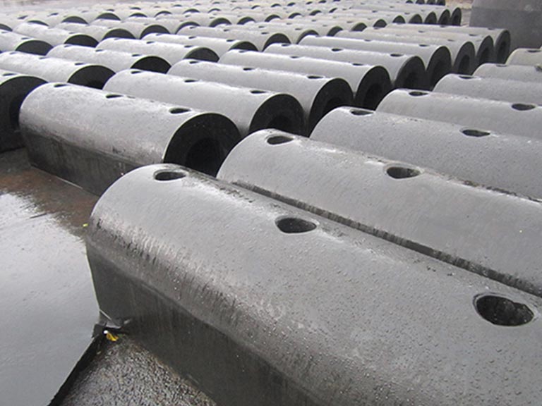
Vessel geometry determines spacing. Verify this against your project layout. Many facilities use rule-of-thumb spacing based on fender width. However, checking gaps against the smallest expected vessel is safer. End treatment matters, too. Sharp ends start tears. Plan for end caps or rounded terminations. Leave a controlled gap between fenders if thermal movement or flex is expected. Do not force tight butt joints.
Pre-Installation Verification Table (Use on Site)
Check Item | What to Confirm | Why It Matters | Evidence to Record |
|---|---|---|---|
Contact height range | Highest/lowest hull contact band | Prevents mounting errors | Marked line photos, notes |
Mounting face condition | Flatness, corrosion, dirt | Ensures bearing + sealing | Photos before/after cleaning |
Fixing feasibility | Through-bolt vs anchor access | Avoids mid-install redesign | Sketch, anchor plan |
Hole placement | Rebar/plate locations | Prevents structural damage | Scan results or notes |
Hardware package | Material, washers, locks | Reduces loosening/rust | BOM, material IDs |
Sealing plan | Sealant type + location | Controls water ingress | Sealing checklist |
Fixing Methods: Hardware Packages and When to Use Them
Select a fixing method based on substrate type, holding capacity, and movement. Most installations use bolt-through, anchor/embedded, or rail systems. Using the wrong category causes failure. The goal is a tight, sealed, and serviceable package.
Bolt-Through Mounting
Through-bolting works when you have rear access. The substrate must carry the load. This allows direct clamping force control. It makes replacement predictable. On steel, confirm the backing plate thickness is adequate. Protect edges against corrosion. On concrete, ensure the detail permits full pass-through.
Anchors or Embedded Plates
Use anchors or embedded plates when you lack rear access. This is common for retrofit quay walls. Follow the manufacturer’s instructions for anchor type and embedment. Hole quality is critical, especially for bonded systems. Degraded concrete may require remediation before installation.
Sliding Rail or Suspended Setups
Tides or floating pontoons may require movement. A fixed-bolt fender may not maintain the right contact line here. Rail systems help with maintenance. Suspended setups allow movement while keeping alignment. These systems add metal components. Corrosion protection and inspection are vital. Ensure the movement path does not pinch the rubber.
Fixing Strip Inserts
Many profiles use an internal fixing strip. This distributes load and prevents crushing. Common materials include stainless steel, aluminum, or rigid polymer. The strip must fit the profile correctly. It must align with drilled holes. A missing or poor strip causes fasteners to pull into the rubber.
Installation Workflow: Marking, Drilling, Fixing, Sealing
A strict workflow reduces rework: mark, drill, prepare, position, tighten, and seal. Common mistakes occur when drilling starts before the layout is locked. Do not tighten before the fender is aligned. Work in segments. Confirm each passes basic checks first. Use safe lifting methods. Avoid damaging rubber edges with sharp tools.
1) Positioning and Temporary Fixing
Begin at a measurable reference point. Hold the fender in position. Confirm it aligns with the marked berthing line. If using a fixing strip, insert it now. Confirm it sits flat. Install a few temporary fasteners to hold alignment.
2) Drilling and Hole Preparation
Drill holes matching the specified fastener system. Keep holes perpendicular to the mounting face. Use PPE and control debris. Verify hole diameter and depth for anchors. Clean holes thoroughly after drilling. Dust and moisture reduce holding capacity.
3) Cleaning and Fit-Up
Clean the mounting face and holes. This ensures the sealant performs well. Remove debris with a brush and air. Keep the area dry if required. If using solvents, check compatibility with coatings. You need a clean interface for mechanical fixing and durable sealing.
4) Progressive Tightening
Tighten fasteners in a cross pattern. This sets the fender evenly. It shares the load across the fixing strip. Use the project torque specification. Do not guess. Over-tightening deforms rubber; under-tightening causes loosening. Tighten in stages. Check alignment after each pass. If the profile twists or bows, stop and correct it.
5) Sealing and Edge Finishing
Apply sealant where water can enter. Seal around penetrations and profile edges. Use a marine-grade sealant suitable for the conditions. Apply it consistently. Install end caps carefully if used. Avoid sharp transitions. A well-finished edge reduces maintenance later.

Verification and Troubleshooting
Installation isn’t complete until you verify alignment, security, and sealing. Schedule rechecks based on operating conditions. Initial checks catch installation errors. Re-torque catches hardware settling. Routine inspections look for loosening, misalignment, or tearing. Keep records to track changes.
Acceptance Checklist
Verify the fender line matches the berthing line. Ensure adjacent units maintain gaps. Confirm all fasteners use the correct washers and locking methods. Inspect sealant for full coverage. Check rubber surfaces for cuts or handling damage.
Retorque Timing
Retorque timing depends on hardware and loads. Follow the maintenance plan. A common practice is rechecking after initial settling and early berthing. Record torque verification and visual conditions. These notes form your baseline for future inspections.
Symptom-to-Cause Checks
Diagnose issues by matching symptoms to causes. Check alignment, fasteners, and sealant first. Review if the fixing method matches the substrate. Inspect end details where tears often begin.
Troubleshooting Table (Fast Field Use)
Symptom | Most Likely Causes | First Checks | Typical Corrective Actions |
|---|---|---|---|
Missed hull contact | Layout ignored contact band | Check rub marks vs. line | Reposition sections |
Loosened hardware | Under-torque, vibration | Check torque, lock nuts | Retorque, upgrade locks |
Rubber distortion | Over-tightening, bad strip | Inspect profile shape | Re-seat strip, retighten |
Water ingress | Poor sealing, dirt | Inspect sealant continuity | Clean and reseal |
Edge tearing | Sharp edges, no end caps | Inspect transitions | Install caps, round edges |
Early corrosion | Wrong material, coating damage | Inspect hardware material | Replace, improve sealing |

Conclusion
Dependable D type rubber fender installation relies on correct alignment and fixing methods. Control tightening and sealing carefully. Treat layout, prep, and progressive tightening as core controls. Plan an acceptance check and re-torque schedule. Record your findings. This keeps maintenance proactive and prevents recurring repairs.
FAQ
What spacing should I use for D type rubber fenders?
How do I choose the correct D fender size?
Can I install D type rubber fenders with adhesive only?
What hardware material works in marine environments?
How often should I inspect and re-torque?
What are common installation mistakes?
Talk to our team.
Share a few details about your project — vessel, port, or operation. We'll reply within 24 hours.