Home » Knowledge Base » Rubber Fenders Technology » The Ultimate Guide to Arch Rubber Fenders
Category Rubber Fenders Technology

The Ultimate Guide to Arch Rubber Fenders

Arch rubber fenders are one-piece moulded rubber units bolted to a quay face through a reinforced foot on each side […]

The Ultimate Guide to Arch Rubber Fenders

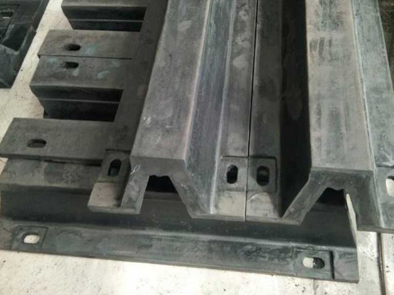
Arch rubber fenders are one-piece moulded rubber units bolted to a quay face through a reinforced foot on each side of the arch, suited to berths where shallow projection and rugged, directly anchored construction matter more than the higher energy efficiency of a cone or cell system. Selection turns on the assembled projection, the manufactured variant, and whether the quoted energy and reaction figures state the conditions they were measured under. Height, length and the fixing arrangement are set at manufacture. The stated conditions decide whether a catalogue line describes your berth at all.

Arch fender specificationWhat published data shows
Height rangeRoughly 150–1,000 mm across published supplier catalogues
Unit lengthVaries by manufacturer and height; published tables list maximum lengths up to about 3,500 mm — take final length and anchor spacing from the manufactured drawing
Steel reinforcementPlacement depends on product design: reinforcement around the mounting points, plus an additional plate in the fender head on panel and face-pad variants
UHMW-PE pad thicknessAbout 30–60 mm across one published catalogue family, rising with fender height; other makers publish wider ranges
Manufactured variantsRubber-face; head-plate for a bolt-on UHMW-PE pad; head-plate connected to a steel frontal panel or pile
MountingBolted horizontally or vertically; ends square or bevelled; corner units made to order
Governing design documentPIANC Fender Guidelines 2024 (MarCom WG 211), covering design, manufacture and testing of fender systems for seagoing vessels at berths, superseding WG 33 (2002)

Ranges above are read across published supplier catalogues and differ between makers. Take the governing figures from the supplier’s drawing for the model quoted.

What is an Arch Rubber Fender?

Arch rubber fenders are linear fender units whose energy capacity comes from compression of an arched cross-section, which suits berths with limited projection from the quay face and vessels in the small to medium size range. The profile is a development of the older V-type rubber fender, with a wider foot and a deeper radius at the leg-to-base transition.

The unit is moulded in one piece and fixed through a foot at each side of the arch, so the load path runs through both feet and straight into the quay face. That geometry gives the type its longitudinal shear tolerance and its low parts count. It also fixes the important dimensions early: bolt pattern, height, length and end treatment are all decided before the unit is cast.

Where a project is chasing the highest energy absorbed per unit of reaction force, cone and cell systems generally have the advantage. Arch units are chosen where a directly anchored, shallow, low-parts-count fender fits the berth. Confirm the clear projection available at the berthing line first. It caps the height, and the height caps the energy.

Arch-Rubber-Fender-2

Reading an Arch Fender Datasheet

Catalogue energy and reaction figures for an arch fender describe one declared test condition, and they hold only for the compression speed, temperature and contact angle printed beside the table. Published fender catalogues commonly report performance at about 23 ±5 °C and a 0° compression angle, then supply velocity, temperature and angular factors to be applied separately for anything else.

Read the basis of the table before applying any factor. Some catalogues publish slow-speed constant-velocity data, some publish rated performance already corrected to a stated approach velocity, and catalogues rebuilt under the 2024 guideline publish Base Fender Performance — the term WG 211 uses for the declared starting figure, before any correction factor is applied. Applying a velocity factor to a figure that already contains one corrects the same effect twice.

Manufacturing tolerance carries a second trap. Published catalogues state a tolerance of about ±10%, applied as plus ten on reaction and minus ten on energy, and the two do not cancel. For the structural check on the quay, the realistic pairing is the low end of energy with the high end of reaction, so a single printed line understates both the fender needed and the load the embeds carry.

When a reaction figure is read as though it already includes site temperature, the outcome is usually a bolt group or panel sized under the real peak, and the correction arrives after the embeds have been cast. Before quoting, we compare the requested conditions against the factors that belong to the compound actually supplied.

What variesCatalogue basisEffect on the figuresWhat to request
Reporting basisConstant-velocity, rated, or WG 211 Base Fender PerformanceDetermines which factors are already inside the numberWhich basis the table uses, in writing
Berthing velocityRated at a stated initial approach velocityRubber is viscoelastic, so faster contact raises reactionThe velocity factor for the compound being supplied
TemperatureCommonly about 23 ±5 °CCold service stiffens the unit and lifts reactionThe temperature factor table for the same compound
Contact angleCommonly 0°Angled contact lowers absorbed energy on a linear unit; vertical and horizontal components apply separatelyAngular factors stated for both axes, not one combined number
Manufacturing toleranceCommonly about ±10%Reaction plus, energy minus, within the same batchWhether the quoted table is before or after tolerance
Test basisType approval testing under the current guidelineA design guideline is not a product certificateThe test report, its date, and who witnessed it

Converting a corrected figure into a design value is a separate step. The current guideline applies partial factors and accounts for contact on more than one fender at a time, and that calculation belongs to the berth designer working from site berthing data.

Contact Faces on an Arch Fender

The vessel-contact arrangement on an arch fender sets the friction and marking behaviour of the whole system, and the choice depends on hull type, berthing frequency and whether a frontal panel is carried. The variants share the same arch profile. What changes is whether a head plate is moulded in, and that cannot be added afterwards.

Manufactured variantVessel contactsSuitsConfirm before ordering
Rubber-face arch fenderRubber directlyGeneral cargo and workboat berths where restraining vessel movement is wanted and marking is not a concernWhether recorded damage came from impact or from sliding
Head-plate arch fender with bolt-on UHMW-PE padThe padHigh-frequency berthing, steel hulls, and berths needing non-marking, low-friction contactPad thickness against the clear projection available
Head-plate arch fender connected to a frontal panel or pileThe panel face, usually itself faced with UHMW-PEBerths spreading load across a panel over several unitsPanel weight, tidal travel and whether chains or other restraints are required

A high-friction rubber face restrains relative movement between hull and quay, and the same friction raises the shear demand carried by the fender body, the feet and the anchorage. Bolted UHMW-PE pads are the usual arrangement because the pad can be unbolted and replaced without disturbing the unit. Permanently bonded rubber-to-polyethylene composites also exist, and on those the face is not a separately replaceable part.

Pad thickness changes geometry, and that arithmetic is worth doing before a drawing is signed. A 500 mm arch unit with a 50 mm pad projects about 550 mm from the quay face, roughly a tenth more standoff than the bare unit. Substitute your own values in the same way: fender height plus pad thickness equals the assembled projection, then compare that against the clear distance your berthing line and existing embed pattern allow. On a retrofit, that difference often decides whether the same bolt line can be reused. The example runs on published catalogue dimensions and carries no site data, so work it again on the drawing you are quoted.

Hull marking has at least two mechanisms behind it, and the pad only addresses one cleanly. Transfer from the rubber contact surface stops when a non-marking face is fitted. Abrasion caused by the vessel sliding along the face is reduced by the lower friction but not removed, and where the sliding comes from mooring restraint, a pad will not fix it.

Arch-Rubber-Fender-4

Which Arch Fender Variables to Lock First

Two arch fender variables have to be settled before any embed is cast, because both are fixed once the unit is moulded and the concrete is poured: the assembled projection, and whether a head plate is included. They lock first because they are the inputs to the embed layout, not because they outrank the others in the calculation. The whole set has to converge together.

A different rubber grade may fit the same nominal geometry, but it is not interchangeable on that basis alone. Changing grade moves energy capacity, reaction force and rated deflection together, which in turn moves anchor loads and hull contact pressure. Where the bolt pattern is identical, the structural check still has to be repeated.

Before embeds are set, these items have to be fixed rather than assumed:

  • Model and height, and the final manufactured length
  • Anchor bolt count, size and spacing, and end distances
  • Rubber grade and the design reaction it produces
  • Whether a head plate is moulded in
  • The load path from vessel to panel to fender to structure

Angled contact deserves its own line in the specification. An arch unit tolerates shear well but cannot rotate to follow a flared bow, so where contact is consistently off square, energy actually absorbed sits below the printed figure before temperature and velocity are even considered. Ask for the angular factors and apply them to the axis vessels actually approach on.

On a low-frequency berth with light craft and no history of shear damage or hull marking, a smaller rubber-face arch unit is often a suitable starting configuration, subject to the berthing energy and hull pressure checks. Adding a pad and a frontal panel there can add cost without removing a failure mode that berth actually has.

Arch-Rubber-Fender-3

What the 2024 PIANC Fender Guidelines Changed

The design document behind arch fender performance data changed in March 2024, which affects what a current quotation should be built on. PIANC Fender Guidelines 2024 (WG 211) completely supersedes the 2002 guidelines and covers design, manufacture and testing of fender systems for seagoing vessels at berths.

The guideline describes the berthing process with higher velocities, lower berthing angles and multiple fender contact, and it moves from the older single global safety factor to a partial factor approach. In its publisher’s own summary, it puts the safety more in the rubber than in the supporting structure. It also states that specifications cannot simply have the old report number swapped for the new one, and that site-specific berthing data tends to give slightly smaller fenders, while ignoring local knowledge risks overdesign.

The two-year transition period for suppliers to reorganise catalogues under the new guideline ended on 1 May 2026. That deadline concerned catalogue data and type approval testing. It did not create a certificate, and a supplier claiming compliance should be able to name the document edition and produce the test report behind it.

Action: ask which guideline edition the quoted arch fender performance table is built on, and whether fender performance testing for type approval has been repeated against it.

Where Arch Fenders Wear Out First

Arch fender service life is usually decided at the anchorage and the exposed ends rather than in the rubber body, so an inspection routine that follows the fixings and the splash zone will catch more than one that looks at the face. On berths taking repeated angled or sliding contact, shear demand concentrates at the fixings at each end of the unit. That is the part of the assembly worth reaching first.

“Maintenance-free” is a marketing description, not a service instruction. Bolts can loosen under repeated compression cycles, washers and embeds corrode in a splash zone, and rubber degradation from sunlight and ozone shows as surface crazing well before energy capacity drops. A bolt-on pad is replaceable on its own, which is why it earns its cost on a high-frequency berth: the wearing part comes off without the unit.

Inspection intervals belong in the supplier’s installation and maintenance manual, adjusted for berthing frequency, exposure and the port’s own inspection regime. Any abnormal berthing event is a trigger regardless of interval. Take the fixing sequence and re-tensioning requirement from the same document.

Arch Fender Decisions Before the Embeds Are Cast

Of everything above, the assembled projection and the head-plate decision are the two that cannot be reversed once concrete is poured, and the rated performance table is the one document that has to be read with its conditions attached before anything is compared.

Where a selection of this type goes wrong, the cause is more often a projection that no longer fits once the pad is added than the rubber grade itself. Berthing velocity, contact angle and the lowest service temperature at the site stay project-level variables, and a fender chosen against a rated line without them has been chosen against a laboratory. Turning those corrected figures into a design value, and setting fender spacing along the quay, is berth-level design work under the current guideline rather than anything a product page can settle. We align the quoted performance table with the guideline edition it was tested under before it goes into a proposal.

If clear projection at your berthing line is already tight and the marking history is on light hulls, size the arch unit first and count pad thickness inside the projection. If the berth carries a frontal panel, start from the head-plate variant and check panel weight and restraint separately; our rubber fenders range covers both fixing arrangements within the same size families.

Have a project in mind?
Tell us what you're working on — we'll reply within 24 hours.

FAQ

Can arch fenders be mounted vertically?
Yes. Bolting is horizontal or vertical, and the choice usually follows tidal range and how vessels sit against the face.
What is the difference between an arch fender and an element fender?
An arch fender is a continuous arched section fixed through a foot on each side, and it can work directly against the quay. Element fenders are modular leg units with a fixing plate at each end — one end to the structure, the other to a panel. Catalogues sometimes list both in one family, so check the drawing before the name.
How long does an arch rubber fender last?
Service life depends on berthing frequency, splash-zone exposure and the compound’s ageing behaviour, so a figure quoted without those conditions is not a prediction for your berth. Ask for ageing data on the compound supplied, and for the pad replacement interval as a separate number.
Can an arch fender replace a cylindrical fender at the same berth?
Rarely as a direct swap. Arch and cylindrical fenders use different fixing patterns, so embeds usually have to be redrilled and the projection changes with them.
Is a corner unit just a straight fender cut to an angle?
No. End treatment is moulded in, so cutting a straight unit on site shortens the distance from the end to the first anchor bolt. Send the corner angle and both quay face dimensions with the enquiry.
Get in touch

Talk to our team.

Share a few details about your project — vessel, port, or operation. We'll reply within 24 hours.

ISO 9001 & 14001 ABS & CCS 80+ countries
Email
[email protected]
WhatsApp
+86 133 5542 0555
Replies within 1 hour, business hours
Scroll to Top

Get Your Free Quote Now

Request a quote today and unlock expert solutions for your marine operations!