

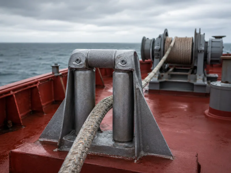
A roller fairlead is a shipboard mooring fitting that guides a rope through a change of direction on rotating rollers instead of a fixed surface. Selection turns on two figures: the safe working load the position can carry, and the range of fleet angles the rope will sweep there. Standards families such as ISO, JIS, DIN and CB fix geometry, material grade and a ceiling SWL. None of them fixes the load a particular deck will support. IMO guidance makes the hull’s build date decide which rule set applies at all, and the rolling advantage lasts only while the bearings turn.
What a Roller Fairlead Does on a Mooring Deck
A roller fairlead sits between the ship’s side and the winch or bollard that holds the line, and it earns its place only where the lead turns sharply enough that a static surface would chafe the rope. The rollers convert sliding contact into rolling contact. Sliding friction adds localized heat to abrasion. How much that heat matters depends on rope material, construction, tension, and how long the line moves under load. That is why the mooring rope specification belongs in the fitting decision.
IMO draws the boundary in a place that catches buyers out. Under MSC.1/Circ.1175, shipboard fittings mean bollards and bitts, fairleads, pedestal rollers and chocks. Any weld, bolt or other fastening connecting the fitting to the supporting hull structure is part of the fitting. The supporting hull structure is the part of the ship that directly receives the forces exerted on it. The seat weld belongs to the fitting.
This article covers the fitting at one mooring position. How many positions a vessel needs, and where they sit, belongs to mooring arrangement design under MSC.1/Circ.1619, which is a separate engineering review.
Why a Seized Roller Can Become a Severe Rope-Wear Hazard
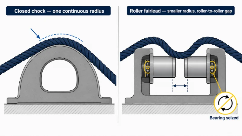
A seized roller can present a harsher sliding contact than the fixed fitting it replaced, depending on roller diameter, surface condition, and the rope’s path through the frame. The reasoning is geometric, and it is conditional. A closed chock presents one continuous radius sized for the rope. A roller fairlead spreads the same turn across rollers of smaller individual diameter, separated by gaps where the roller ends meet the frame.
While the rollers turn, that smaller radius costs nothing, because the rope never drags across it. Once a bearing binds, the rope may slide over a radius tighter than the chock would have offered, and across the roller-to-roller transitions as well. Whether that is worse depends on how the two radii compare in the specific pairing. A large, smooth, seized roller can still beat a small or scored chock throat. The mechanism that makes a roller fairlead gentler in service is the mechanism that makes its failure mode sharper.
In berths with a large tidal range, where a lead stays loaded in one direction, the axle and bearing chamber are usually among the first parts needing re-inspection. The roller never completes a full rotation in that service, so the same bearing arc carries every load cycle. ISO 13742:2020 requires that all rotating parts be greased. That is a manufacturing requirement, and keeping them greased at a position nobody can reach with a grease gun becomes the owner’s problem. Decide the fitting and the maintenance plan together.
Roller Fairlead Types: What the Standard Number Fixes and What It Leaves Open
Roller fairlead standards are organised by geometry and material, so a standard number fixes shape, nominal size and steel grade while leaving rope compatibility, fleet angle and installed SWL to the project.
| Fitting | Lead function | Current edition | SWL basis | Confirm before ordering |
|---|---|---|---|---|
| Warping / guide roller | Single change of direction on deck, usually feeding a winch or capstan | ISO 13755:2020 (steel rollers); JIS F 2014; DIN 81906; NS2585 | Table value is a ceiling; installed value set by foundation and under-deck reinforcement | Roller diameter against actual rope diameter; whether a rope guide is needed to stop the line jumping off when slack |
| Shipside roller fairlead | Leads the rope from inboard to outboard through the bulwark or side | ISO 13767:2020 (supersedes 13767:2012, withdrawn 2020) | As above | Two-roller vs three-roller construction; that the SWL reaches the towing and mooring plan |
| Universal / horizontal roller fairlead | Accepts the rope from a range of directions using vertical and horizontal rollers | ISO 13742:2020 (without upper roller); ISO 13733:2020 (with upper roller); JIS F 2026; CB/T 3062; DIN 81902 | As above; ISO 13742:2020 carries a normative annex on strength assessment | Type and nominal size against the real angular envelope; gap size relative to rope diameter |
| Pedestal fairlead | Raises the lead point to align with the winch drum and take heavier off-axis loads | ISO 13776:2020 (supersedes 13776:2012, withdrawn 2020); DIN 81907; CB/T 436-2000 | As above | Pedestal height against actual rope height; under-deck reinforcement at the seat |
Two cautions on that last column. DIN designations circulate under trade descriptions that do not always match the official titles, so check a DIN reference against the DIN catalogue and not the supplier’s page. Material requirements also sit inside the standards. ISO 13742:2020 specifies frame and roller plate with a yield point of at least 235 N/mm², rising to 315 N/mm² for nominal sizes 400A, 400B and 400C. Axles are carbon steel at 345 N/mm² minimum, and bushes are brass, bronze or equivalent. A quotation naming that standard has committed to those figures whether or not it repeats them.
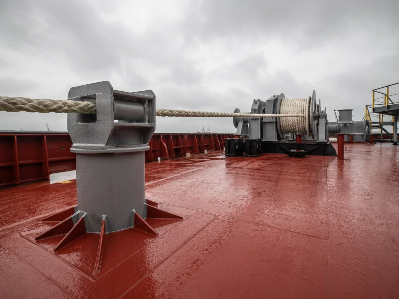
The rope-side check is newer than most buyers’ habits. ISO 13742:2020 §7.3 requires that fitting and line selection account for the ratio between the fitting’s contact diameter D and the rope diameter d, to reduce bend loss of strength. §7.4 adds that rope tensile strength may fall with the bend radius, in line with the rope manufacturer’s guidelines. Neither clause existed in the 2012 edition. The second edition’s change list records §7.3 as newly added technical guidance.
Read the dates together and the consequence is uncomfortable. A fitting sized under the 2012-generation drawings was fully compliant without anyone checking what the ratio did to the rope, because the standard did not ask. Carry that size across to a synthetic line, thicker than a wire rope of equal strength and less tolerant of a tight radius, and the selection is compliant and unchecked at once. Work the D/d ratio out from the specific nominal size against the specific rope, then check it against the rope maker’s bend-loss guidance. The extremes of the standard’s size range will not give you the answer.
The Two Variables to Confirm First: Installed SWL and Fleet Angle
Installed SWL and fleet angle should be settled before roller count, material grade or standard family, because either one can invalidate a selection that is otherwise correct on paper. Both are fixed once the seat is welded. The rest can still move inside the specification.
Four terms get used interchangeably. They are not interchangeable.
| Term | Used by | What it is |
|---|---|---|
| MBLSD | IMO documents | Ship design minimum breaking load: the minimum breaking load of new, dry mooring lines for which shipboard fittings and supporting hull structures are designed |
| SDMBL | OCIMF / MEG4 | The same design basis, written with the letters in a different order |
| LDBF | OCIMF / MEG4 | Line design break force — a property of the rope you buy, set at 100–105% of the design basis |
| SWL | IMO / ISO | The safe load limit of the fitting for mooring in harbours or sheltered waters |
The rule chain runs in a surprising direction. MSC.1/Circ.1175 §4.6.1 sets the SWL, for marking purposes, equal to the ship design minimum breaking load of the mooring line. §4.3.1.1 sets the minimum design load on supporting hull structures at 1.15 times that same figure. §4.4.1 allows fittings to be selected from an industry standard accepted by the Administration, at least on that basis. ISO adds conditions on the actual SWL carried on board. It must account for the foundation and the under-deck reinforcement, and it must be marked on the towing and mooring plan. It must never exceed the SWL given in the standard.
So the design basis is a constant of the hull, not of the rope currently rove. Fitting stronger lines does not raise mooring capacity. It moves the intended failure point off the rope and onto the fairlead and the structure beneath it. A rope purchase cannot update the fairlead’s basis.
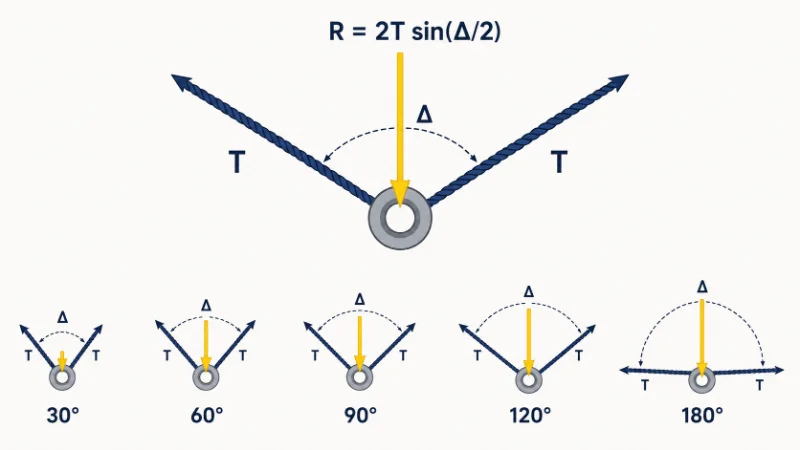
Fleet angle is the second gate, and IMO names it directly. The towing and mooring arrangements plan must state, for each fitting, the limiting fleet angle: the angle of change in direction of a line at the fitting. That angle is a load variable, and the reason is arithmetic. Where the line takes a turn, the design load on the fitting equals the resultant of the design loads acting on the line, capped at twice the design load on the line. For equal tension T in both legs and a change of direction Δ, that resultant is R = 2T · sin(Δ/2):
| Change of direction Δ | Resultant on fitting |
|---|---|
| 30° | 0.52 T |
| 60° | 1.00 T |
| 90° | 1.41 T |
| 120° | 1.73 T |
| 180° | 2.00 T |
A 100 t line tension redirected through 90° does not put 100 t on the fairlead. It puts about 141 t, before the structural factor in §4.3.1.1 reaches the supporting structure.
The twice cap in the circular repays a close reading, because it is not a rounded safety allowance. The function 2 · sin(Δ/2) reaches 2 only at Δ = 180°, where both legs pull the same way and the fitting takes both tensions in line. IMO’s ceiling is the geometry written as a rule. A designer who treats it as margin has misread a mathematical maximum as a cushion.
Two consequences follow. A fitting selected only for the loaded-condition lead may take a different roller contact pattern in ballast, so check the full horizontal and vertical envelope against the manufacturer’s geometry and allowable fleet angles. The plan’s SWL provisions also apply to no more than one mooring line. A position that may see two is outside the marked figure.
Build date decides which rule set applies. MSC.1/Circ.1175/Rev.2, approved on 28 August 2025, applies to ships constructed on or after 1 January 2028. Rev.1 covers ships constructed on or after 1 January 2024 but before 1 January 2028. The original circular still covers ships constructed on or after 1 January 2007 but before 1 January 2024. Three windows, not two. A fitting specified against the wrong window is a documentation problem before it is an engineering one.
When a Closed Chock Is Still the Right Answer
A closed chock remains the better fitting where the lead runs in one direction, the load is largely static, and inspection intervals are long, because the rolling advantage is collected only while somebody maintains the bearings. On an inland barge, a workboat on a fixed berth, or any position where the line is set once and left alone, a compliant closed chock is enough. The friction saving of rollers will not repay the maintenance they bring.
A fixed lead does not by itself make a chock acceptable. Its contact radius, surface condition and D/d compatibility with the selected line still need verifying against §7.3 of the applicable standard, and the mooring arrangement analysis still governs.
The dividing line is dynamics, not vessel size. Tidal range, swell exposure, frequent adjustment under tension, and synthetic line all push toward rollers. A stable load path with a fixed angle pushes back toward the chock. Positions between those two descriptions are where the general arrangement earns its keep.
Maintenance obligations run in parallel either way. MSC.1/Circ.1620 covers inspection and maintenance of mooring equipment including lines, and applies to existing and newly built ships alike. Choosing rollers accepts that obligation at a specific position. Choosing a chock lowers it without removing it.
Where to Start with Roller Fairlead Procurement
Two answers settle most of a roller fairlead specification: the SWL the position can support once foundation and under-deck reinforcement are accounted for, and the full fleet-angle envelope the rope will sweep there. Standard family and roller count resolve once those two are on paper.
When a table SWL is carried from a standard into a purchase order without the under-deck check, what shows up later is rarely the fitting. It appears as deformation in the deck structure around the seat, and it gets corrected by local reinforcement while the part that was blamed goes back on the shelf.
Bring these nine inputs to an enquiry:
- Vessel type, size and build date — the 2007 / 2024 / 2028 thresholds decide which IMO guidance applies
- Mooring rope in service: material, construction, diameter and LDBF, or the MBL<sub>SD</sub> if calculated
- Fleet angles at the position, horizontal and vertical, minimum and maximum through the tidal and loading range
- Required SWL, and whether foundation and under-deck reinforcement have been assessed or still need checking
- Standard family and edition the yard or owner works to, plus nominal size if fixed
- Mounting interface: weld-on seat, bolted base, or bulwark-integrated, with deck plate thickness
- Classification society, and which specific certificate or approval is required
- Surface treatment and corrosion protection appropriate to the trade area
- General arrangement or mooring plan extract showing the position
With those nine, the conversation starts at the specification instead of the catalogue. Zhonghaihang Shipping Supply works from the mooring plan and the rope data before quoting, and where the under-deck check has not been done, we say so before putting an SWL on the page.
FAQ
Is a roller fairlead the same thing as a warping roller?
What certification should be specified for a roller fairlead?
Where is a roller fairlead’s SWL recorded on board?
Can an existing roller fairlead be reused when converting from wire rope to synthetic lines?
Does a retrofit on an older hull follow the older guidance?
Talk to our team.
Share a few details about your project — vessel, port, or operation. We'll reply within 24 hours.