


The structural design of pneumatic fenders is set by ISO 17357-1:2014 for the high-pressure family: a cylindrical air bag with hemispherical heads, built from outer rubber, synthetic-tyre-cord reinforcement and inner rubber, all firmly vulcanised. Part 1 rates those fenders at 50 kPa or 80 kPa initial internal pressure. Low-pressure fenders sit under Part 2 and use coated textile panels instead. Within Part 1, what varies between suppliers sits below the layer count. Ply schedule, bead ring construction and end configuration are laminated into the body, and they close before vulcanisation.
| Parameter | Requirement under Part 1 (high pressure) |
|---|---|
| Body construction | Outer rubber, synthetic-tyre-cord layers, inner rubber, all vulcanised firmly (6.1.1) |
| Rated initial internal pressure | Pneumatic 50 at 50 kPa, Pneumatic 80 at 80 kPa (4.2) |
| Types | Type I net-type, Type I Single, Type II sling-type (4.1) |
| Steel at the flange opening | Less than 0.20 × fender diameter (6.1.6) |
| Mandatory safety valve | Diameter 2,500 mm and above; below that, only if ordered (6.1.7) |
| GEA deflection | Guaranteed energy absorption obtained at (60 ± 5)% deflection (7.3.3) |
| Reaction force tolerance | ±10% at GEA deflection (7.3.4) |
| Prototype confirmation | Every ten years, evaluated by a major classification society (8.1) |
| Low-pressure equivalent | ISO 17357-2:2014, coated textile panel construction, 7 kPa unless otherwise specified |
Clause numbers refer to ISO 17357-1:2014. ISO confirmed both parts of the standard as current in 2024.
What ISO 17357-1 Fixes in the Structural Design of Pneumatic Fenders
ISO 17357-1:2014 fixes body construction for every high-pressure floating pneumatic rubber fender sold as compliant, with the requirements keyed to pressure class. The standard covers material, performance and dimensions for fenders that berth and moor a ship to another ship or to a berthing structure. It also sets the test and inspection procedures. Part 1 and Part 2 together cancelled and replaced ISO 17357:2002, which now carries withdrawn status.
Each layer in the body has a defined job. The outer rubber protects the cord layers and the inner rubber from abrasion and other external forces. Its compound has to meet the tensile and tear values tabulated in Part 1, and the material test report is where those values appear. The inner rubber seals the pressurised air. The reinforcement layers, made of synthetic-tyre-cord fabric, hold the internal pressure and establish the fender’s endurable pressure.
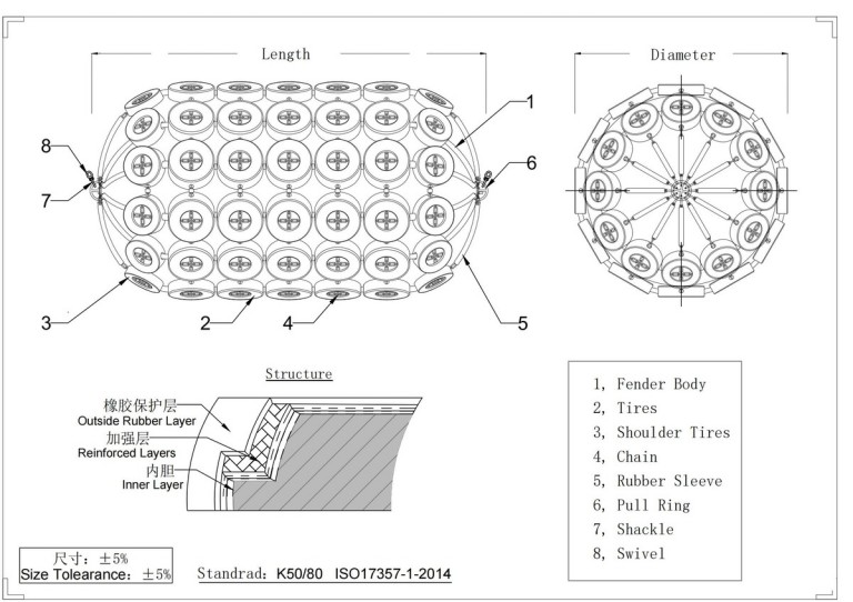
The cord fabric choice is structural. The main fibres of synthetic-tyre-cord are not braided the way canvas or belt fabric is, which changes how the layer behaves in fatigue resistance and pressure holding. Ply schedule also varies within a range. Inside one qualified design family, a smaller diameter may carry fewer plies. Ask for the ply schedule on the approved drawing for your own diameter, and treat a count quoted from another size as unconfirmed.
Part 2 low-pressure fenders are a separate product rather than a de-rated version of this body. They use longitudinal panels of coated textile with hemispherical ends attached, and Part 2 adds two more pneumatic fender types, clamped end and moulded end, carrying 7 kPa unless otherwise specified. Everything below describes Part 1 construction.
Why 50 kPa and 80 kPa Are Grades, Not Ceilings
Rated initial internal pressure is the grade at which an uncompressed fender operates, not the pressure its body can withstand. The standard tabulates the two as separate values, and both change with size and pressure class. Endurable pressure has its own definition: the inner pressure at which a fender bursts. Four pressure values sit in the same table for every size, and a quotation can name any one of them.
Pressure inside the body climbs as the fender deflects, which is why each of those values is quoted against a stated grade or a stated deflection. The figure on the plate marks where the working curve begins.
| Term on the quotation | What it actually states | What to do with it |
|---|---|---|
| Initial internal pressure (50 or 80 kPa) | The grade an uncompressed fender operates at | State it on the order and hold it in service |
| Endurable pressure | The inner pressure at which the body bursts | Read it from the Part 1 pressure table for your size |
| Safety-valve setting pressure | The pressure at which the valve relieves | Confirm it matches the size and grade in the same table |
| Hydraulic test pressure | The pressure used in the hydrostatic test | Ask which fenders it was applied to under Clause 9 |
| Hull pressure at GEA deflection | Inner pressure at rated deflection, carried by the hull | It tracks the pressure grade, so the Pneumatic 80 figure differs from the Pneumatic 50 figure for the same size |
| Reaction force at GEA deflection | Air pressure multiplied by the contact area | Compare quotes on the same deflection basis before comparing the numbers |
So the grade is an operating set point to maintain, not a performance-tuning variable. Guaranteed energy absorption, reaction force and hull pressure are all declared against a stated grade. Run a fender away from that grade and it sits outside the performance data it was sold on.
Read the plate figure as a safety ceiling and the error compounds quietly. A fender topped up to it on a hot afternoon, with no note of conditions, goes back into service above its intended starting point. Log ambient temperature alongside every pressure reading, so the next check compares like with like.
Bead Rings, Flange Openings and the 2,500 mm Valve Threshold
Metal parts at the ends of a pneumatic fender are sized against an over-compression case rather than against rated duty, and the steel allowance scales with diameter. Part 1 requires the ends of the reinforcement cord layers to enter the bead ring and turn up outside it. It limits the bead ring, and any other steel around the flange opening, to less than 0.20 D. That limit keeps metal parts safe from permanent deformation when compression approaches 80%.
Set that against the performance clause, where guaranteed energy absorption is obtained at (60 ± 5)% deflection. Two clauses, two different questions. The 0.20 D geometry rule guards flange-end metalwork under severe over-compression, roughly twenty percentage points past the rated deflection. The GEA figure on the datasheet answers something else. Put your own diameter into the same expression: 0.20 × D gives the value the steel has to stay under, so a 3,300 mm fender has to come in below 660 mm.
Type I Single addresses the same over-compression case through end configuration. That variant carries a flange opening at one end only, with no metal parts at the other, so the metal-free end cannot deform permanently under heavy compression. A practical installation implication follows: orient that end toward the position where severe end over-compression is credible. The choice is made before the body is built.
The valve threshold has an edge worth reading twice. Sizes absent from the pressure tables must satisfy the requirements of the next larger diameter, so a 2,200 mm fender inherits the pressure requirements of a 2,500 mm one. The safety-valve clause is keyed to actual diameter, whatever pressure class the size borrows. A 2,200 mm unit therefore carries 2,500 mm pressure requirements while sitting below the diameter that makes a valve mandatory. Neither clause states that outcome directly; it falls out of reading the two together, which is why the ordering clause includes a line for requesting a safety valve on fenders under 2,500 mm.
The valve itself is a component adapted to the flange opening rather than a layer inside the laminate. What closes before vulcanisation is the flange arrangement and the provision made for the valve. Whether a valve can be added later depends on that arrangement, and the manufacturer should confirm it.
Maintenance & Upkeep
Regular maintenance and inspections are required to ensure the long-term stability of pneumatic fenders. The following is a complete maintenance guide that covers inspection frequency, inspection items, and inflation pressure management.
- High Usage Frequency: If they are used regularly. Then, the fender pressure should be checked every three months and inflated as needed.
- Low Usage Frequency: For less regular use, pressure checks and maintenance can be performed every six months.
- Surface Inspection: Periodically inspect the surface of the fender for cuts, abrasions, or perforations. This verifies that the exterior rubber is intact.
- Metal Fittings Inspection: Check metal fittings like chains and shackles for rust or deterioration. Rusty metal fittings can shorten the life of a fender and compromise its safety.
- Pressure Detection: Check the pressure at least once a month to ensure it is within the safe limit specified on the fender (50kpa/80kpa).
- Inflation Valve Inspection: Inspect the inflation valve for damage or leaks. Then, repair or replace any that are problematic.
- Flange Nut Inspection: Ensure that the nuts on the flanges at both ends of the fender are secure and rust-free, ensuring the safety of the connections.
- Sheath Inspection: Inspect fenders with sheaths for any damage. The sheath’s integrity is critical to protecting the inside rubber layers.
- Regular Inflation: To ensure proper internal pressure, inflate the fenders on a regular basis, according to usage.
- Pressure Monitoring: Use a pressure gauge to routinely check the pneumatic fender’s pressure to ensure it remains within the recommended range. Excessive and insufficient pressure can both have an impact on fender performance and longevity.
Which Structural Decisions Close Before the Drawing Is Released
Structural decisions split into those built into the vulcanised body and those that stay serviceable components or set points. Only the second group remains open after delivery.
| Decision | Open after manufacture | Depends on |
|---|---|---|
| Diameter and length | No. Sets ply schedule, bead ring geometry and the valve threshold | Berthing energy demand and the standoff the fender must hold |
| Rated pressure class | No | Energy and hull-pressure targets for the berth |
| End configuration and type | No | Where over-compression is credible; whether a protection net is used |
| Reinforcement ply schedule | No | The manufacturer’s qualified design for that diameter |
| Flange arrangement and valve provision | Settle at order. The valve is a serviceable flange component | Whether accidental over-compression is credible; retrofit depends on flange arrangement |
| Body colour | Specified at order; black applies by default | Marking and visibility requirements |
| Net, tyres, guy chains and ropes | Yes. Replaceable in service | Quay face condition and handling method |
| Inflation pressure | Maintained at the rated grade and checked in service | The grade specified and the temperature at which the reading is taken |
The variables converge together, but diameter and rated pressure class lock first. Ply schedule, bead-ring geometry and the mandatory-valve question all take them as inputs. And the laminate they produce cannot be changed economically once vulcanised.
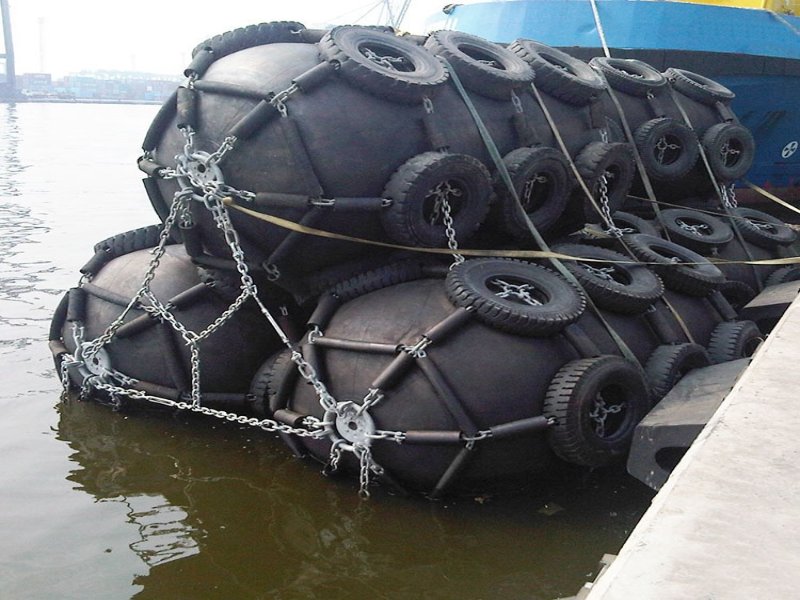
On rough or stepped quay faces, the chain-tyre net and its tyres act as an additional sacrificial layer. They take abrasion and localised contact loads that would otherwise land directly on the outer rubber, and they are the part of a net-type fender to re-inspect first.
Not every duty justifies this construction. Where a small workboat lies against a smooth pontoon, and the fender never has to float, hold a large standoff or be deflated for transport, a foam-filled or solid rubber unit answers the same problem without the pressure-management routine.
Reading Pre-Order Evidence Against Order-Specific Inspection
Test evidence for a pneumatic fender comes in two layers, and the certificates a purchaser reviews before ordering are not the records generated for the fenders actually supplied. Under the ordering clause, a purchaser can ask for a prototype fender test certificate covering the Clause 8 tests. A major classification society evaluates it, and it has to date from no more than ten years before the enquiry.
The same clause covers historical commercial evidence and sets the range that evidence speaks for. The commercial inspection and test certificate must come from a fender of diameter equal to or larger than the one being enquired about, at the same or higher internal pressure, and from within ten years. Coverage therefore runs in one direction: a larger, higher-pressure unit stands as evidence for a smaller, lower-pressure enquiry, so a certificate for a 2,500 mm fender at 50 kPa carries no weight for a 3,300 mm unit at 80 kPa. That reading follows from the range the clause sets, rather than from a separate rule about the reverse case.
Prototype exemption works on a different axis. A prototype test is required for each fender involving different methods of basic construction or design. The exemption for smaller diameters applies only where the basic design, construction and fabrication methods are the same, and where the ply count differs because of the diameter. The qualifying condition is design-family sameness.
Clause 9 sits apart from all of that. It governs inspection and testing of the commercial fenders themselves, covering the rubber material test, dimensional inspection, air-leakage and hydrostatic-pressure testing. Confirm which of those apply to every fender, which are sampled, and against which purchase-order requirements. When we compare two quotations, the diameter and pressure printed on a pre-order certificate get checked against the diameter and pressure being ordered before the rest of the document is read.
What Locks First in a Pneumatic Fender Body
In the structural design of pneumatic fenders, diameter and rated pressure class lock first. Ply schedule, bead-ring geometry and the mandatory-valve question all follow from them, and none of the three survives a change of mind after vulcanisation. Nets, tyres and the inflation set point stay open afterwards. The laminate does not.
Damage that shortens a fender’s service life can also come from conditions that never reached the order: berth geometry, localised end over-compression, a contact case nobody described at enquiry. Which of those applies is a project-level check.
If the diameter you need is absent from the standard’s pressure tables, settle two points before the drawing is released. First, which larger diameter sets your pressure requirements. Second, whether you are specifying a safety valve that diameter alone will not oblige. Send those two answers with your berthing energy figure, and we will align the pneumatic fenders drawing and the certificate range to them before manufacture begins.
FAQ
Does the standard set how many cord plies a fender must have?
Does a chain-tyre net change the body construction itself?
What has to be stated on the purchase order?
Does the standard tell you which fender size a berth needs?
Talk to our team.
Share a few details about your project — vessel, port, or operation. We'll reply within 24 hours.