

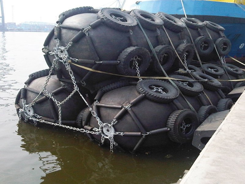
A Yokohama fender is a floating pneumatic rubber fender: an air-filled marine fender used between a vessel and a jetty, or between two vessels alongside each other, whose energy absorption depends on diameter, length and initial internal pressure rather than on the brand name it carries. Fenders of this class are built and tested to ISO 17357-1:2014, which covers high-pressure units at 50 kPa and above and defines two pressure grades, P50 and P80. The name is used loosely across the industry, so the label alone tells a buyer very little. Which unit belongs at a given berth depends on vessel displacement, approach velocity at first contact, and the reaction force the berth structure can accept.
What a Yokohama Fender Is ?
The Yokohama fender name covers a family of floating pneumatic rubber fenders rather than one fixed product, and whether a given unit suits a berth turns on its size and pressure grade. The type came out of the Yokohama Rubber Company in Japan, and the history of the name explains how it spread from there into general use. The precise term is floating pneumatic rubber fender, or Yokohama-type pneumatic fender. Listings often spell it yokahama or yokohoma; these refer to the same product. Yokohama is also still a company name, so a buyer checking provenance should confirm the actual manufacturer and the ISO documentation rather than read origin into the term.
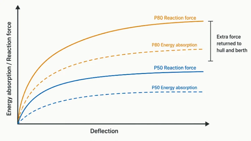
Treating the name as a single specification is the expensive mistake. Two units carrying it can differ by an order of magnitude in the energy they absorb and in the force they push back into a hull.
A pressure grade carried over from an earlier project, because the vessel class looked similar, is the common route to that error. The fender arrives correctly marked and still returns more reaction force into the berth than the structure was designed to take. The first corrective step is to repeat the fender-system selection against verified berth data. Depending on what that shows, the outcome may be a different pressure grade, a different size, more units, a revised arrangement, or a limit on approach speed.
What Air as the Working Medium Sets, and What It Limits
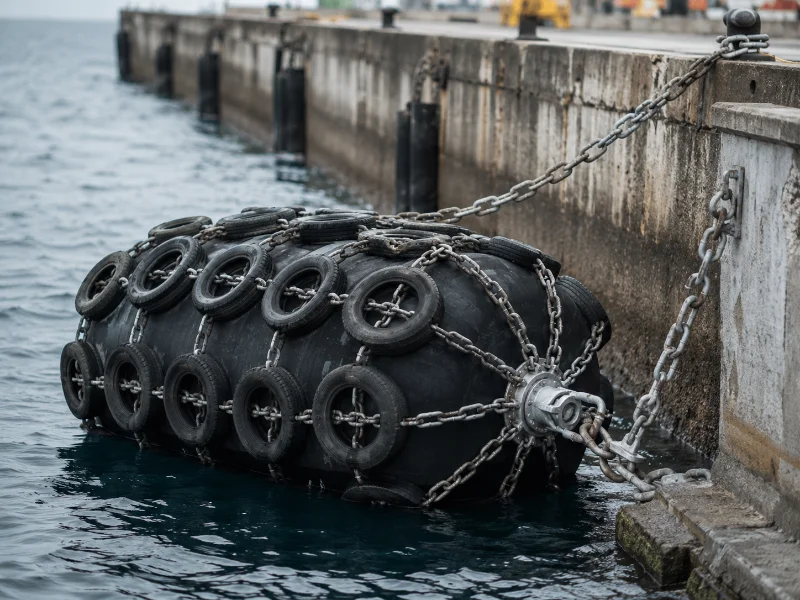
Because a pneumatic fender absorbs impact by compressing sealed air rather than by deforming solid rubber, its energy absorption, its hull pressure and its failure mode all trace back to one variable: the internal pressure it holds at the moment of contact. The body is straightforward. An inner rubber layer seals the air, synthetic cord-reinforced layers carry the load, an abrasion-resistant outer layer takes the wear, and end flanges close each end and carry the inflation valve. Under ISO 17357-1:2014, fenders of 2,500 mm diameter and above must carry a safety valve to release excess pressure under accidental over-compression.
Air also lets the fender conform to a hull as it compresses, spreading the contact so that hull pressure and reaction force stay comparatively low. That matters most where two hulls meet obliquely, as they do in ship-to-ship work. Yokohama Rubber’s technical catalogue reports no reduction in energy absorption for its pneumatic fenders under inclined compression up to 15 degrees, in the configurations tested. A solid block loses performance as the angle opens up. Whether a particular unit behaves that way is a question for its own type-approval data.
Air behaves differently from rubber in one respect that rarely reaches product literature. Pressure in a sealed body of roughly fixed volume rises and falls with absolute temperature. A fender inflated on a cool quayside and then left in direct sun is no longer sitting at the pressure it was set to. That makes the measurement procedure part of the specification: readings should be taken and interpreted using the manufacturer’s inspection and temperature-correction method, and a reading outside the permitted range needs investigating. Warm weather is not an explanation for it. The safety valve is a separate matter. On fenders of 2,500 mm and above it limits pressure during accidental over-compression, which is a mechanical event rather than a thermal one.
Pneumatic Against Foam and Solid: Where Each Type Wins
A pneumatic body suits large vessels and oblique ship-to-ship contact better than foam or solid rubber, though the right choice at a given berth depends on unit size, inspection access, and whether anyone will realistically check pressure on a schedule.
| What it decides | Pneumatic (Yokohama-type) | Foam-filled | Solid rubber |
|---|---|---|---|
| Behaviour under overload | Reaction force rises progressively, within rated compression and valve capacity | Progressive | Can stiffen toward a rigid block |
| Hull pressure | Low, spread across the contact | Low | Tends to be higher for comparable energy |
| Oblique / STS contact | Holds performance under inclined compression | Good | Falls off as the angle grows |
| What puts it out of service | Loss of air through a breach in the skin | Skin damage; no air to lose | Wear, and failure at the fixings |
| Routine attention | Periodic pressure checks | Minimal | Minimal |
| Typically suits | Large vessels, STS, wide tidal range | Smaller sizes, limited inspection access | Fixed quay faces |
These are screening-level tendencies for narrowing a shortlist. They do not replace project-specific performance calculations, and any row can be overturned at a particular berth by design energy, contact area, tidal range, shear and abrasion exposure, puncture risk, spares availability or whole-life cost.

The overload row repays following through, because it redistributes risk instead of removing it. When a solid fender stiffens under excess load, the energy it stops absorbing arrives in the hull plating and the quay face as reaction force. A pneumatic body goes on absorbing further into the stroke, though not without limit: it has a rated compression, its flange geometry has a design envelope, and its safety valve has a finite venting capacity. So the binding question on a pneumatic unit is usually about the force it returns, and sizing up is not automatically the safer move.
At the smaller end of the range, and at berths where nobody is realistically going to check pressure on a schedule, a foam-filled unit is often the better buy. There is no air to lose, and both types can usually be sized for the energy involved at that scale. Whether that holds at a given berth still depends on design energy, available contact area and whole-life cost, and cost comparisons run in both directions depending on size and quantity.
Net Type or Sling Type: Matching the Fitting to How the Fender Will Be Handled
Fitting type is a separate decision from size and pressure, and it turns on how often the unit will be moved and how much abrasion the berth will put on it. Net type fenders sit inside a chain, wire or fibre net, usually with tyres or rubber sleeves, which suits fixed and semi-permanent positions where abrasion is the main threat. Sling type units carry a lifting device at each end connected by guy chain or rope, weigh less, and are quicker to recover and redeploy.
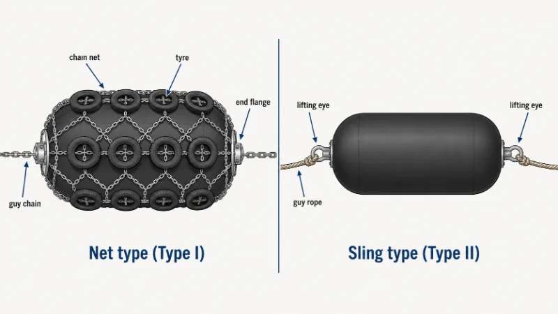
The practical question is redeployment frequency against abrasion exposure. A fender that stays on one berth for years earns its net. One that moves between operations, or gets recovered ahead of weather, is easier to live with as a sling type, provided the lifting arrangement on site can handle it.
On tidal berths with a wide water-level swing, the guy chain and the end-fitting shackles tend to be the parts that come up for re-inspection first. They carry the cyclic movement the fender body is there to absorb. How that fitting is then rigged, meaning chain length, attachment points and stand-off geometry, is a separate exercise from choosing the fender and belongs with the berth’s installation drawings.
Sizing and Pressure: Which Variable to Confirm First
Sizing a Yokohama fender starts from berthing energy rather than from a diameter, and berthing energy is set by the vessel’s displacement, its approach velocity at first contact, and the contact geometry at the berth. Two documents divide the work. ISO 17357-1:2014 governs the product: construction, minimum performance, dimensions, testing and documentation, including guaranteed energy absorption for standard sizes. Project-level selection is a separate engineering exercise, governed by the berth design criteria and by guidance such as PIANC Report No. 211, PIANC Fender Guidelines 2024, which covers the design, manufacturing and testing of fender systems and supersedes the earlier WG 33 guidelines. The product standard specifies two initial pressure grades, P50 at 50 kPa and P80 at 80 kPa. For the same nominal size, P80 offers higher guaranteed performance and raises reaction force and hull pressure with it. Select it only where those figures stay inside what the berth structure and the hull can accept.
Approach velocity at first contact is the variable to pin down first. In the basic kinetic relationship behind berthing energy, energy scales with the square of velocity and only linearly with mass, so an assumed approach speed moves the answer further than an assumed tonnage does. Project design energy is more than that expression. It also carries the added-mass, eccentricity, softness and configuration coefficients and the safety factors the governing design method requires. The asymmetry between velocity and mass survives into it. PIANC’s 2024 guidelines make the same point from the other direction. Site-specific berthing data, taken from pilots and harbourmasters instead of assumed, can justify a smaller fender than a generic figure would; ignoring it tends to produce an overdesigned one.
| Variable | What it sets | When to confirm it | Changeable after manufacture? |
|---|---|---|---|
| Approach velocity at first contact | Berthing energy, scaling with the square of velocity | First | No |
| Vessel displacement | Berthing energy, scaling linearly | First | No |
| Allowable reaction force at the berth | Constrains the whole system: grade, size, quantity, spacing, arrangement | Before any grade or size is fixed | No |
| Hull pressure limit for the vessel class | Constrains grade, size and contact area | Before any grade or size is fixed | No |
| Diameter and length | Guaranteed energy absorption available | Once the design energy exists | No |
| Fitting type (net or sling) | Handling effort and abrasion resistance | Last | Sometimes, subject to body design, end fittings and manufacturer approval |
Published Yokohama fender size ranges vary by manufacturer. What decides anything is the guaranteed energy absorption on the datasheet for the specific unit, read against a design energy figure.
ISO 17357 Compliance and What to Check on Delivery
ISO 17357-1:2014 is the standard a Yokohama-type fender is certified against, and it governs the product: material, performance, dimensions, and the test and inspection procedures behind the certificate. It was reviewed and confirmed in 2024 and remains current. Part 2 covers low-pressure fenders, and the two parts together replaced the 2002 edition, so references to other years in product listings are worth checking against the current text. PIANC sits on the other side of that line. Its 2024 guidelines govern how a system is designed, manufactured and tested for a berth. PIANC also states plainly that it certifies nothing, so a listing advertising “PIANC certified” fenders is describing something that does not exist.
One requirement in the 2014 revision repays reading for what it implies. The standard limits the diameter of the bead ring and other steel around the flange opening so that the metal does not take a permanent set when the fender is compressed close to 80 percent. A requirement framed that way treats near-limit compression as something a working fender will meet. What follows from it is an inference rather than a clause. Because the flange and bead geometry is controlled specifically for severe compression, those areas belong in the manufacturer-approved inspection after a heavy contact. An intact outer skin says little about them. The standard also expects prototype performance confirmation to be repeated on a ten-year cycle, which is a question about the model being offered rather than about the individual unit.
Unfolding a fender on the quayside and checking it against the order takes an hour. Discovering at the berth that the pressure grade marked on the body is not the one the berthing-energy calculation assumed costs considerably more.
- ISO 17357-1:2014 conformity marked on the body, with standard and year legible
- Prototype and commercial test certificates, including air-pressure and hydrostatic records
- Nominal size, P50 or P80 grade and serial number, checked against the order rather than the catalogue
- Safety valve fitted where diameter is 2,500 mm or more, with its setting recorded; settings and valve design vary between manufacturers
- End flange, valve seat, shackles, swivels and net or sling condition once unfolded
- Independent inspection or classification-society review where the purchaser, terminal, charterer or project specification requires it
We verify these against the order and the berthing-energy inputs before a unit ships. ISO conformity confirms that the product complies. Whether it suits a particular vessel, berth or ship-to-ship operation is a separate engineering determination, made against berthing energy, reaction-force limits, hull pressure limits and the operating conditions at that berth.
Where to Start When Specifying a Yokohama Fender
Two figures decide most of a Yokohama fender specification: the approach velocity at first contact, and the reaction force the berth structure can accept. Diameter, pressure grade and fitting type all follow from those. A specification that names a size without naming those two has skipped the step that determines whether the fender fits the berth.
The specifications that cause trouble later rarely name the wrong diameter. They carry a pressure grade across from an earlier job because the vessel class looked similar, and the mismatch surfaces later as reaction force at the berth. Where a figure depends on the berth, we confirm it at project level, and at Zhonghaihang the berthing-energy check and the ISO documentation are treated as part of the specification.
Before working through a full Yokohama pneumatic fender selection, settle three things on your own side: the design approach velocity at first contact and where that figure came from, the allowable reaction force for the berth structure, and the hull pressure limit for the vessel class that will use it. Those three bound the answer. A datasheet only means something once they exist.
FAQ
How much does a Yokohama fender cost?
Can a punctured fender be repaired?
How often should internal pressure be checked in service?
Does an ISO 17357 certificate cover the classification-society requirement?
Talk to our team.
Share a few details about your project — vessel, port, or operation. We'll reply within 24 hours.