

The global pneumatic fender market is expanding across commercial shipping, offshore energy, and port infrastructure — but for procurement teams and port engineers, the variables that determine whether a fender system performs as specified are technical: which ISO 17357 part applies, how berthing energy is calculated for the actual vessel class, which configuration suits the operational scenario, and what acceptance criteria confirm performance before deployment.
Scope: This guide addresses high-pressure floating pneumatic rubber fenders under ISO 17357-1:2014 and low-pressure variants under ISO 17357-2, for commercial berthing, ship-to-ship transfer, and offshore mooring. It does not cover hydro-pneumatic fenders for submarine docking or fixed solid rubber fender systems, which operate under distinct load-transfer mechanisms.
Performance Definitions and the ISO 17357 Standard Framework
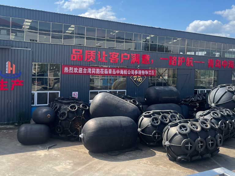
Pneumatic fenders are cylindrical, air-filled elastomeric devices that absorb kinetic energy between a vessel hull and a berthing structure. Their defining characteristic is high energy absorption relative to reaction force: the inner air chamber deflects under contact, compresses, and dissipates impact energy across the hull contact surface. Internal pressure must remain within the defined working range — deviation in either direction shifts both energy absorption output and reaction force away from the values in the rated performance curve.
Two ISO 17357 parts govern specification. ISO 17357-1:2014 covers high-pressure floating pneumatic rubber fenders, with 50 kPa and 80 kPa as the standard initial pressure grades within this category — both are high-pressure grades, not a low/high classification split. ISO 17357-2 applies to low-pressure floating pneumatic rubber fenders, a distinct product class with separate performance parameters and acceptance requirements. Confirming which Part applies before evaluating any supplier’s test documentation is the necessary first step in procurement.

Why Calculated Berthing Energy Must Drive Fender Specification
The most consequential fender specification error is treating dimensional size as a proxy for energy absorption capacity. Berthing energy scales nonlinearly with vessel displacement: ULCVs and LNG carriers generate energy states that can exceed a fender arrangement designed for smaller vessel classes, even when the physical fender dimensions appear adequate. When teams carry forward configurations from earlier projects without recalculating for the actual vessel in service, the typical result is deflection beyond the rated performance range — reaction forces exceeding quay structure or hull design limits, accelerated outer cover wear, and service life shorter than specification.
The corrective path is the PIANC berthing energy methodology: confirming effective vessel mass, establishing defensible approach velocity assumptions, and selecting size and configuration so that absorbed energy stays within the rated performance curve. The PIANC 2002 guidelines remain the widely used baseline, covering effective mass coefficients, eccentricity, water cushion, and softness factors. The updated PIANC WG211 guidelines (2024) should also be reviewed where moored-vessel response under environmental loading, or vessel range across tidal states, materially affects the fender design.
Approach velocity is the most sensitive input in this calculation — final values require local berthing records, tug-assist protocols, and site exposure classification. A planning reference of 0.10–0.30 m/s for large vessels under controlled conditions is a reasonable early estimate, but it should not be used as a substitute for site-specific data in the final specification.

Global Market Demand Variables and Growth Outlook
Pneumatic fender demand is growing across commercial shipping, offshore energy, and port infrastructure, with published market estimates varying significantly by scope definition and methodology.
| Item | Representative direction |
|---|---|
| Market size (2026 est.) | Commonly cited around US$0.43 billion across multiple analyses |
| Forecast range (early 2030s) | Approximately US$0.55–0.68 billion, varying by scope |
| Reported CAGR range | Approximately 3.2%–6.7%, depending on category definition and forecast horizon |
| Leading region | Asia Pacific — port infrastructure density and shipbuilding concentration |
| Faster-growth areas | Middle East, Africa, Southeast Asia — port construction and LNG terminal investment |
Estimates diverge because some reports cover only floating pneumatic fenders while others aggregate broader marine fender categories. Any figure used for planning should be checked against the scope assumptions of the source. Four structural drivers appear consistently across available analyses:
- Fleet scale escalation: The ongoing transition to ULCV, New Panamax, and LNG carrier vessel classes increases berthing energy per docking event, driving replacement and recalibration demand at terminals handling larger vessels.
- Port infrastructure expansion: Greenfield and capacity-expansion projects across Asia Pacific, the Middle East, and Africa are generating primary installation demand for ISO-compliant fender systems.
- Offshore energy operations: FPSO units and LNG transfer terminals require fenders rated for sustained environmental loading; the low reaction force profile of pneumatic systems is critical where platform or hull structural margins are tightly managed.
- ISO-aligned procurement standards: ISO 17357 compliance is increasingly a baseline requirement in commercial port, STS, and offshore terminal tender specifications where third-party testing and traceable acceptance data are mandatory.
Application Scenarios and Configuration Selection
The three primary use cases carry distinct requirements for energy absorption capacity, surface protection, and deployment flexibility:
| Application | Key performance requirement | Preferred configuration |
|---|---|---|
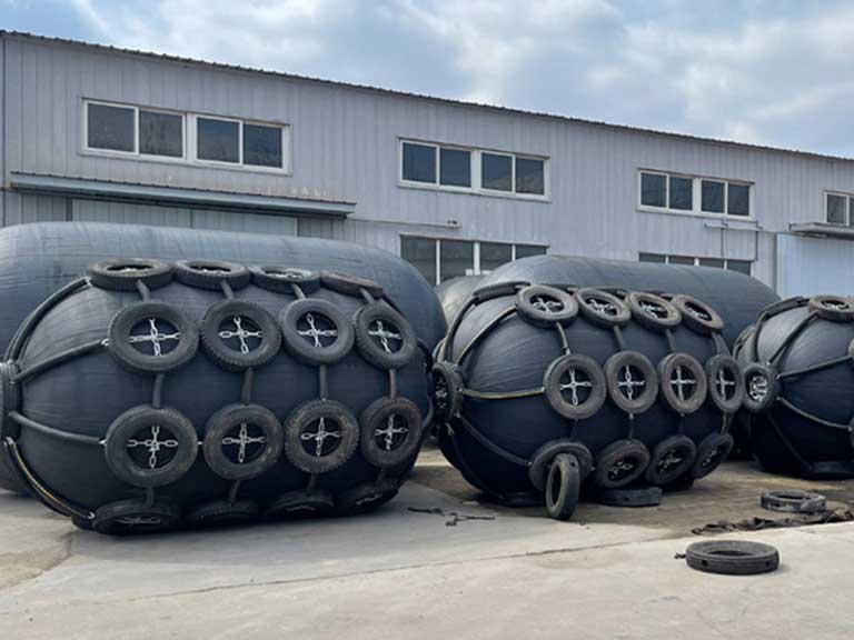
| Ship-to-ship (STS) transfer | Floating stability, freeboard adaptability, high energy absorption | Sling-type or tire-chain net, sized to vessel displacement |
| Ship-to-dock (quay) berthing | Abrasion resistance, consistent reaction force, fixed anchoring | Tire-chain net; rope net for lighter or lower-frequency applications |
| Offshore / FPSO mooring | Environmental loading resistance, UV/ozone stability | Sling-type; verify for wave height and current exposure |
In STS operations, the fender must maintain stable hull contact under differential freeboard conditions throughout the cargo transfer cycle — as the loaded vessel rises and the receiving vessel settles, relative hull heights change continuously. A fender sized only for initial contact geometry may lose consistent engagement mid-operation, which is why freeboard differential range is a standard item in our drawing review. It directly determines required fender diameter and sling configuration, and it is frequently absent from initial procurement scopes.
For ship-to-dock applications at high-frequency commercial terminals, tire-chain net configurations distribute outer cover wear more uniformly under repeated hull contact than rope net alternatives; the appropriate choice depends on berthing frequency and hull coating sensitivity.
ISO 17357 Acceptance Criteria and Procurement Verification
Acceptance criteria should be defined before the order is placed. The checklist below covers the key verification items for high-pressure floating pneumatic rubber fenders under ISO 17357-1:
| Acceptance item | What to verify |
|---|---|
| Standard applicability | ISO 17357-1 (high-pressure) or ISO 17357-2 (low-pressure) confirmed pre-order |
| Initial pressure grade | 50 kPa or 80 kPa, matched to rated performance curve for the application |
| Energy absorption | Guaranteed value at rated deflection, confirmed by factory test report |
| Reaction force | Within berth structure capacity and vessel hull pressure limits |
| Rated deflection test | Performance confirmed at specified deflection after conditioning sequence |
| Material test records | Inner rubber, cord reinforcement, outer cover test data provided |
| Third-party certification | BV, DNV, ABS, LR, CCS, or equivalent classification body |
| Pressure retention | Commissioning pressure-hold check per manufacturer’s installation manual |
| Accessories scope | Net type, chains, shackles, swivels, safety valves, inflation fittings within delivery scope |
The factory test report and the classification certificate from the third-party body are separate documents confirming different things — the former covers performance data, the latter covers process and quality system compliance. Both should be required as part of the delivery record.
Maintenance, Service Life, and Total Ownership Cost
In projects where pressure monitoring is not part of the documented inspection schedule, we typically observe performance degradation occurring ahead of rated service life. Gradual pressure loss from micro-perforations or valve seepage goes undetected until visible deformation appears at the berth — at which point the fender is already operating outside its rated performance range. For detailed inspection procedures and scheduling, refer to our pneumatic fender maintenance guide. Total ownership cost includes initial procurement, pressure monitoring, periodic inspection, accessory maintenance, and eventual skin replacement — and this maintenance burden scales with berthing frequency and environmental severity in ways consistently underestimated at the procurement stage. A pressure check schedule calibrated to operational conditions should be established at commissioning, not left to ad hoc practice.
Service life planning varies by conditions. A conservative 8–10 year figure is standard in commercial procurement; some manufacturers cite 10–15 years under favorable conditions with consistent pressure maintenance, low UV/ozone exposure, and moderate berthing frequency. The appropriate planning assumption should align with the actual inspection and maintenance program — our dedicated guide on pneumatic fender lifespan covers the full range of variables that affect service duration. IoT-enabled pressure monitoring — embedded sensors with remote data transmission — reduces undetected degradation risk at high-frequency terminals, with cost-effectiveness depending on berthing volume, available technical staffing, and maintenance budget structure.

Fender Selection Workflow: Vessel Particulars to Commissioning
Each step produces a verifiable output that becomes part of the project record. For product-specific sizing tables and step-by-step calculations, see our guide on choosing the right Yokohama pneumatic fender.
- Confirm vessel class and effective displacement — include the full vessel range and any planned capacity expansion.
- Calculate design berthing energy — PIANC 2002 baseline; consult WG211 (2024) where moored-vessel conditions or tidal range affect design.
- Define the operational scenario — STS, ship-to-dock, or offshore; this drives configuration and accessory requirements.
- Select pressure grade and fender size — confirm energy absorption at 50 kPa or 80 kPa covers design berthing energy with adequate margin.
- Check reaction force and hull pressure limits — verify against both berth structure capacity and vessel hull pressure tolerance.
- Select net or sling configuration — based on scenario, abrasion exposure, and freeboard variation range.
- Confirm certification and accessory scope — applicable ISO Part, classification body certificate, and full accessory delivery scope.
- Define pressure inspection schedule — commissioning hold test, periodic check intervals, and outer cover inspection criteria before first deployment.
Steps 2 and 5 are where the most consequential specification errors occur in practice; these two points are the focus of our drawing review before any configuration is confirmed.
Conclusion
The pneumatic fender market’s growth is sustained by vessel class escalation, port infrastructure investment, offshore energy expansion, and ISO-aligned procurement standards. Performing well within that market, however, depends on specification discipline at the project level — particularly confirmed berthing energy calculation, correct ISO Part identification, and acceptance criteria defined before the order is placed.
In our experience, the two specification gaps most consistently requiring correction at drawing review are approach velocity assumptions not verified against site conditions, and pressure grades selected by dimensional size rather than performance curve validation. Both are straightforward to resolve early in scope definition.
Share your vessel particulars, design berthing energy calculation, operational scenario, and inspection requirements with our team — we will align on ISO standard applicability, configuration, and acceptance criteria before confirming a recommendation.
FAQ
What is the difference between ISO 17357-1 and ISO 17357-2?
How is berthing energy calculated for fender sizing?
What service life should be assumed for planning?
When should sling-type fenders be selected over tire-chain net?
What third-party certifications should be required?
Why do published market size estimates vary so much?
Talk to our team.
Share a few details about your project — vessel, port, or operation. We'll reply within 24 hours.