


Types of pneumatic fenders are defined across two parts of ISO 17357. Part 1 covers three high-pressure types: Type I net-type, Type I Single, and Type II sling-type. Part 2 covers two low-pressure types, clamped end and moulded end. The type describes end construction and whether a protection net is fitted. Rated initial internal pressure is a separate order parameter: 50 kPa or 80 kPa under Part 1, and 7 kPa unless otherwise specified under Part 2. Chain-tyre nets, aircraft-tyre nets and non-marking grey compounds are supplier options layered on those five types.
Specification snapshot
| Specification point | What ISO 17357 states |
|---|---|
| Part 1 high-pressure types | Type I (net), Type I Single (net, one end with no flange opening and no metal parts), Type II (sling) |
| Part 2 low-pressure types | Clamped end type, up to and including 2.3 m diameter; moulded end type, 2.8 m diameter and above |
| Rated initial internal pressure | 50 kPa or 80 kPa (Part 1); 7 kPa unless otherwise specified (Part 2) |
| GEA measurement basis | Guaranteed energy absorption stated at 60 ± 5 % deflection (both parts) |
| Reaction force tolerance | ± 10 % at GEA deflection (both parts) |
| Safety valve | Required at 2,500 mm diameter and above (Part 1); optional below that, if stated on the order |
| Prototype test validity | Performance confirmation every ten years, evaluated by a major classification society |
| Current status | Both parts published January 2014, last reviewed and confirmed in 2024 |
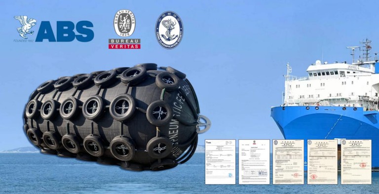
What ISO 17357 Counts as a Pneumatic Fender, and What It Does Not
A pneumatic fender under ISO 17357-1:2014 is a synthetic-cord-reinforced rubber body holding compressed air at a rated initial pressure of 50 kPa or 80 kPa. That definition excludes two products that sit beside it in most supplier catalogues.
A Yokohama fender or pneumatic fender is a strong, durable rubber fender that is filled with high-pressure air. It deflates easily, so it can be moved and reinstalled elsewhere with ease. Foam-filled fenders share that mobility. Their energy comes from a closed-cell foam core inside a polyurethane skin, with no internal pressure to set, monitor or top up.
You should distinguish between pneumatic fenders and marine airbags. Marine airbags are generally used for launching ships, while pneumatic fenders absorb berthing and mooring energy between two hulls or between a hull and a structure. We check the product category against the berthing duty stated on the enquiry before quoting, because a foam fender and a pneumatic fender answer different questions.
Pneumatic fenders are manufactured in several different ways, each with its advantages. The most common methods are moulding and wrapping. ISO 17357 does not classify fenders by production method, and neither method establishes compliance on its own. Compliance comes from the construction requirements, prototype testing and commercial inspection documentation for the specific design and pressure rating.
Pneumatic fenders come in a wide range of sizes, and can also be custom-made to suit a particular berth. Catalogue ranges differ between manufacturers. Take both diameter and length from the supplier’s certified performance table.
Order a fender by trade name and colour alone, with no ISO part, type or rated pressure on the purchase order, and a sling-type unit can arrive at a berth specified for a net-type. That correction is a re-order.
Applications for pneumatic fenders
- Oil and gas tankers
- Fast ferries and aluminium vessels
- Temporary and permanent installations
- Rapid response and emergency
- Naval establishments
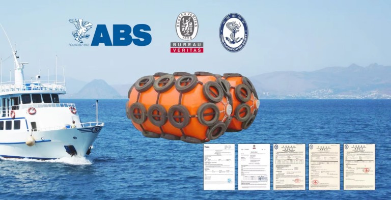
The Five Types of Pneumatic Fenders Defined in ISO 17357
ISO 17357 closes its type list at five entries across two parts. Which entry applies depends first on the rated initial internal pressure the berth needs, then on end construction.
Part 1, Type I: Net-Type
Type I fenders are covered by a chain net, wire net or fibre net. Each end of the longitudinal chains, wires or fibres is linked through rings and connected to a guy-chain or guy-rope. Many ships use pneumatic fenders for ship-to-ship, remote berthing, inclined berthing, and naval activities. That net is what keeps a Type I unit in service against an abrasive quay face or an unfaired hull. Compared to other types of fenders, pneumatic fenders have less reaction force on the ship and the quay structure.
Part 1, Type I Single: Net-Type With One Metal-Free End
Type I Single is a net-type fender with a flange opening at one end only, and no metal parts at the other. The standard’s stated purpose is narrow. Removing the flange and metal components from one end reduces the risk of permanent deformation of end metalwork if severe over-compression occurs. Part 1 requires the bead ring or other steel around a flange opening to stay below 0.20 D for the same reason.
ISO 17357-1 does not designate Type I Single as a fender for routine operation near 80 % compression. Both parts establish performance values at 60 ± 5 % deflection. One practical consequence follows from the single opening. That one end has to carry both the air valve and, at 2,500 mm diameter and above, the required safety valve. Confirm the valve arrangement on the approved drawing.
Part 1, Type II: Sling-Type
Type II fenders carry no protection net, so the fender body itself becomes the direct contact surface. The standard requires a lifting device at each end, connected to a guy-chain or guy-rope. As the sling pneumatic fender does not have a protection net, it has a thick outer layer of rubber. Thanks to this design feature, the chains do not come into contact with the ship or the quay, thus reducing the risk of damage. Whether that outer rubber gives a longer service life than a netted fender depends on the certified construction and the actual contact surface. Against rough concrete or an unfaired hull it may not. In addition, the sling fenders are easy to install and require little maintenance. They can also be used in areas with high or low tidal ranges and maintain sufficient space between the hull and the structure.
Part 2, Clamped End Type
Clamped end fenders are low-pressure units up to and including 2.3 m diameter. The body uses longitudinal panels of rubber-coated textile, sealed at each end by clamped end fittings that also carry the mooring points. ISO 17357-2:2014 locates the inflation fitting so it will not inhibit compression to 60 %. Below 1.8 m diameter it replaces the twin inflation and gauge valves with a single dual-purpose valve.
Part 2, Moulded End Type
Moulded end fenders are low-pressure units of 2.8 m diameter and above. The cylindrical body is coated textile, with hemispherical moulded ends attached by a circumferential seam. Both ends carry a flange opening and end closure assembly, and one of them carries the inflation and pressure-gauge valves.
The five types compared
| ISO part and type | End construction | Rated initial pressure | Confirm before ordering |
|---|---|---|---|
| Part 1, Type I (net) | Flange opening at one or both ends; net of chain, wire or fibre | 50 or 80 kPa | Net material, and whether used tyres or rubber sleeves are fitted |
| Part 1, Type I Single | Net-type; one end with no flange opening and no metal parts | 50 or 80 kPa | How the air valve and any required safety valve share the single opening |
| Part 1, Type II (sling) | Lifting device at each end; no protection net | 50 or 80 kPa | Certified outer rubber properties against your actual contact surface |
| Part 2, Clamped end | Coated-textile panels sealed by clamped end fittings; ≤ 2.3 m diameter | 7 kPa default | Valve arrangement, which changes below 1.8 m diameter |
| Part 2, Moulded end | Coated-textile body with hemispherical moulded ends; ≥ 2.8 m diameter | 7 kPa default | Seam and bead-ring construction at the moulded ends |
Read the two Part 2 definitions together and a gap appears. Clamped end is written as “up to and including 2.3 m”, moulded end as “2.8 m and above”. A low-pressure fender specified between those diameters falls outside both definitions as drafted. Ask the manufacturer which construction and which prototype test the unit is being built and certified against.
Hydro-pneumatic fenders sit outside the five types in a different way. Neither part classifies them, though procurement specifications still borrow Part 1’s figures.
Harness, Tyre and Colour Options Sit Below the Type
Harness and compound options change what the fender touches. The ISO type stays the same. Both are chosen from hull sensitivity and abrasion exposure.
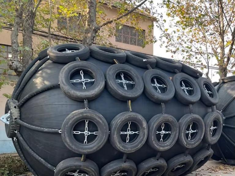
For net fenders, a chain net, wire net or fibre net can be used. In most cases, these nets use old tires and rubber covers for added safety. Reusing tyres this way gives the design a small carbon footprint, and the covered body resists cutting and puncturing from sharp objects. The three net materials differ in mass, flexibility, repair method and corrosion-protection requirement. Compare them on the specified steel grade, coating, chain or wire diameter and replacement method. The net category alone does not settle which resists corrosion better.
Aircraft-tyre nets use larger tyres than standard vehicle tyres. Where the design builds in that geometry, it can add stand-off or shoulder coverage. Check actual dimensions and contact geometry on the approved drawing.
Pneumatic fenders with a grey body and grey harnessing are used where the hull coating is sensitive to visible transfer marks. Non-marking compounds are intended to reduce that risk, and cannot be specified as eliminating it. Surface cleanliness, contact pressure, ageing and net components all affect the outcome. The commercial case is straightforward. Cruise terminals and naval berths specify grey or white units to avoid repeated hull repainting. Part 1 treats fender colour as an order parameter that defaults to black, so the certified material properties of a non-black outer rubber are worth confirming separately.
Supplier codes such as HPF-SCN, HPF-ACN, HPF-GBGH, HPF-SB and HPF-SG resolve back to roughly two ISO-relevant facts: whether a protection net is present, and what the outer compound and tyre colour are. Size and rated initial pressure appear separately on the quotation. Comparing two suppliers on catalogue codes alone therefore compares different things, which is why we resolve every code back to the ISO part, type and rated pressure before pricing.
What the ISO Type Settles, and What the Berth Design Decides
ISO 17357 is a product standard, and it says so about itself. The scope of Part 2 states plainly that it does not address the methods for selecting the correct fender type. Neither part gives you berthing energy, reaction force limits, hull pressure limits or fender spacing.
That selection framework changed recently enough to affect live enquiries. PIANC Fender Guidelines 2024 (MarCom WG 211) was published in March 2024 and completely supersedes the 2002 WG 33 guidelines. PIANC states that users cannot simply substitute WG 211 for WG 33 in an existing specification, because the design approach differs. WG 211 describes berthing with higher velocities, lower berthing angles and multiple fender contact, and it strongly recommends site-specific data over the tabulated values.
Action: the transition period for suppliers to reorganise catalogues against the new guidelines ended on 1 May 2026. If your fender specification still cites WG 33, check with the specifying engineer which guideline the current revision is written to before you compare quotations. The two produce different fender sizes from the same berth.

Which Variables to Confirm Before the Fender Is Built
ISO type and rated initial internal pressure have to be settled before manufacture, because both are built into the carcass and cannot be changed once the unit leaves the factory. They are not the first decisions in a berth design. Energy, reaction force, hull pressure and geometry come from the system framework above. But they are the two with no second chance at the product level.
Rated initial internal pressure deserves particular care, because buyers often read it as a tuning range. It is a specified operating condition, not an adjustable performance band. Part 1’s 50 kPa and 80 kPa each have their own performance table, endurable pressure, safety-valve setting and hydraulic test pressure. In service, pressure is checked and restored to the rated value on the fender marking and certificate.
Size deserves the same caution. Where a size falls outside the standard’s performance tables, it has to satisfy the pressure requirements of the next larger diameter. Part 1’s example is a 2,200 mm fender meeting the 2,500 mm requirements, and Part 2 applies the same rule with a 2.5 m fender meeting 2.75 m requirements. In both parts a custom size is a dimensional accommodation, never a route to a lower specification. The safety-valve rule keys off actual diameter instead, becoming mandatory at 2,500 mm and above.
In ship-to-ship work where the two hulls sit at very different freeboards, the guy-chain attachment and the net end rings are usually the first parts to need re-inspection after a season of service.
Ask any supplier for these four documents before shipment:
- The prototype fender test certificate, evaluated by a major classification society and dated within ten years of the enquiry
- The commercial fender inspection and test certificate, covering a fender of equal or larger diameter at the same or higher internal pressure
- The fender marking, showing size, rated pressure and serial number, read against those certificates
- Written confirmation of whether a safety valve is fitted, for any unit below 2,500 mm diameter
Pneumatic fenders can respond well to changes in high tides, and they exert lower mooring forces in bad weather, because the large deflection lets the contact area move with the swell. That is where they earn their cost: tidal swing, freeboard differences, inclined approach, or fenders that move between berths. If your berth is a fixed quay with a predictable tidal range and no ship-to-ship work, a foam-filled or fixed rubber fender is often the cheaper and lower-maintenance answer.
Summary
Across the five types of pneumatic fenders in ISO 17357, the pair that has to be right at order stage is the part-and-type combination and the rated initial pressure. Harness, tyre material, colour and marking can all still be specified afterwards. Those two cannot be revisited once the carcass is built. Everything above them, from energy to hull pressure to spacing, belongs to the berth design, and everything below them is a catalogue option. We clarify which of the three layers an enquiry has already settled before a specification is issued.
If you need to deal with heavy, abrasive duty, a chain-and-tyre net type is the sturdier answer. If you need a lightweight fender that is quick to install, the sling type is. Where your berth runs ship-to-ship transfers against painted or naval hulls, settle first whether the net comes off: Type II with certified outer rubber, or Type I with grey non-marking tyres and sleeves. And if the duty is a wide stand-off with modest energy, check whether a Part 2 low-pressure type fits before pricing high-pressure units. The diameter bands in Part 2 will narrow the answer quickly.
FAQ
Is a Yokohama fender the same as a pneumatic fender?
What size range do pneumatic fenders come in?
Can the same fender be used at both 50 kPa and 80 kPa?
Do fenders under 2,500 mm need a safety valve?
Which ISO part applies to hydro-pneumatic fenders?
How often should pneumatic fenders be inspected in service?
Talk to our team.
Share a few details about your project — vessel, port, or operation. We'll reply within 24 hours.